Washington Macropad
Overview
A macropad shaped like the state of Washington, made for the cKeys Winter 2020 meetup. It supports MX, Alps, and Choc switches as well as a rotary encoder and an OLED display.
Bill of Materials
To build this, you need:
- 8 PCB mount MX or Kailh Choc switches (there isn't a plate, plate mount and Alps switches will work if you make one)
- 1 Pro Micro/Elite-C/Proton-C/etc as well as the included header pins
- 1 EC11 rotary encoder
- 1 128*32 I2C OLED display and included headers
- 8 1N4148 diodes or equivalent
- 8 200-220 ohm resistors
- 8 3mm LEDs (these ones look really nice)
- 1 1k ohm resistor
- 1 AO3416 MOSFET or equivalent
- 1 Alps SKQG switch or other with same footprint
- 16 M2 screws
- 8 M2 standoffs, 8mm length
- Rubber bumpons
For an interactive BOM with references, click here.
Download default firmware
If you participated in the workshop offered at the cKeys Winter 2020 meetup, your controller will come
pre-programmed with an example firmware. If you modified it and want to revert it back to the original
firmware, or if you didn't attend the workshop, you can download this hex file and follow the
instructions in the QMK section to flash it. This is also in the QMK folder,
ckeys/washington, as the default layout.
Download PCB files
Download the gerber files and KiCad project, licensed under a Creative Commons Attribution-NonCommercial-ShareAlike 4.0 International License.
Download zip archiveAssembly
1. Solder SMD components
First, solder the SMD components (the MOSFET and reset switch). These are easiest to solder first, when the PCB can be flat on your table. The MOSFET is very sensitive to ESD, so make sure to ground yourself.
 One pin of the reset switch soldered
 The MOSFET soldered
2. Solder diodes/resistors
Next, solder the diodes and resistors. The components should be on the back of the PCB (the side with the text on it). The footprints for the diodes have one round pad and one square pad; the line on the diode should face toward the square pad. The resistors don't have any polarity, so you can insert them in any direction. Make sure to solder the 1k ohm resistor in R9, and the other resistors in the remaining footprints. To hold the components in while you flip the board around and solder them, I like to use masking tape.
 All of the diodes in place
 A close-up of how the diode should be inserted
 Using masking tape to hold the diodes in
 The diodes soldered with their leads clipped
 All of the resistors inserted except for R9
 The location of R9
 Completed.
3. Solder OLED display
Now, solder the OLED display. Insert the header pins into the top of the board with the long end going through the board, and solder the pins from the back. Cut the excess pin. Next, place the display on top. Hold the display up so it isn't tilted (either using masking tape, putty, your hand, or something else) and solder the four connections.
 The pins soldered on the back
 The display soldered on the front
 The display is level with the board.
4. Solder controller headers
After that, solder the header pins to the board. Insert the header pins into the board from the bottom side with the short side going through the board. The board should hold them in while you solder them.
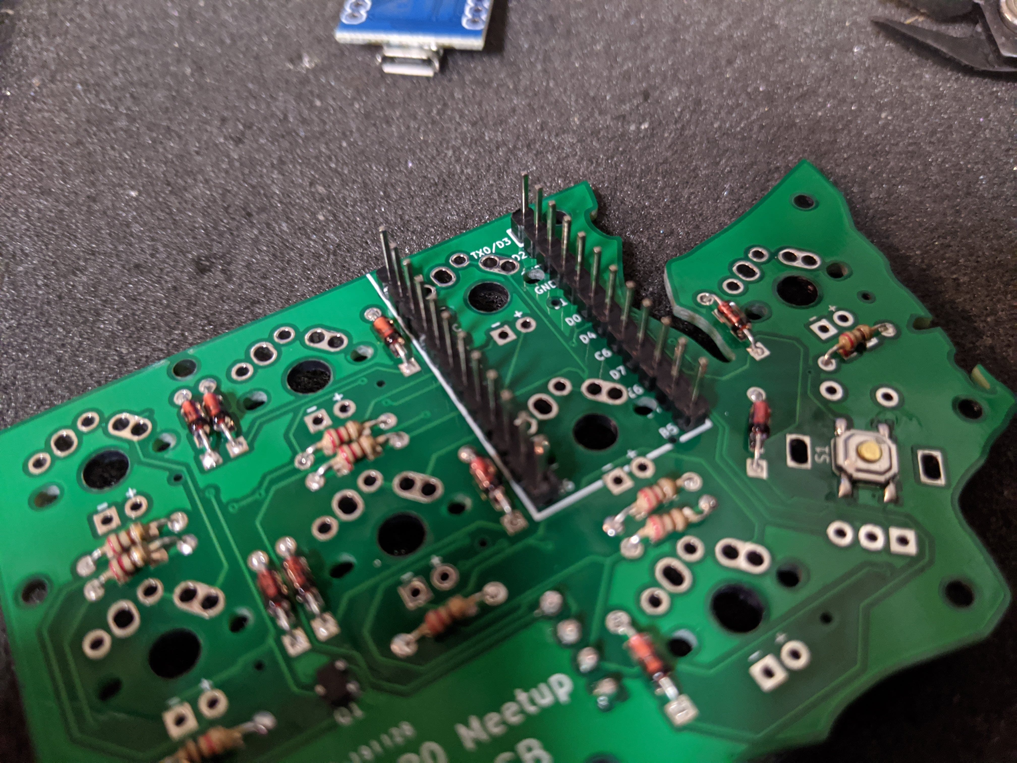 The headers inserted into the board
5. Solder switches
Next, solder the switches. Insert them into all eight positions on the board and solder them.
 The switches
 The switches are soldered
6. Solder LEDs
Now, solder the LEDs. Insert the LEDs into the switches so that the long leg is to the left, solder them, and clip the leads off. I usually solder one leg, and if the LED isn't sitting in the switch correctly, I heat the solder joint while pushing on the LED to get it in the correct position.
 The LEDs in the switches
7. Solder controller
Now that everything is soldered, solder the controller onto the header pins with the chip side facing inwards. If the switch pins touch the controller board, try removing solder from them and cutting them to be shorter. It's also a good idea to put electrical or kapton tape on the component side of the controller if it is very close to the switch pins. Once you're done, clip the excess pin.
 Soldering the pins
 Pins soldered and cut
8. Solder rotary encoder
The final component to solder is the encoder. Insert it into its position from the front and solder the pins on the back.
 The encoder from the front
 The pins on the encoder
9. Program QMK onto controller
QMK is the firmware that runs on the microcontroller inside of the macropad. If you are doing the cKeys workshop, you'll already have firmware on your controller, but if you want to change what it does or have a brand new controller, do the following:
- Go to the QMK Configurator.
- Under the Keyboard dropdown, choose "ckeys/washington".
- Use QMK Configurator to create a keymap for your macropad. If you don't know how to use it, click on the wizard hat icon in the upper right corner of the screen to watch a video tutorial.
- Click the compile button, and once that's done, click the download firmware button. You should get a hex file.
- If you're on MacOS or Windows, download QMK Toolbox. Follow the guide here to flash the firmware, double-clicking the reset button underneath the encoder to activate programming mode. In addition, if you have the default firmware programmed, press and hold the FN key (located on the Olympic Peninsula) and press the key to the left of the OLED display.
- If you're on Linux, I recommend downloading PMFT if you have a Pro
Micro, and dfu-programmer if you have an Elite-C. For a Pro Micro, download the git
repository and run the
linux-install.pyPython script with Python 3. Then, double-click the reset button under the encoder, and runsudo pmft /path/to/file.hex /dev/ttyUSB0, substituting the path to the hex file and the serial port for the correct values. For an Elite-C, install dfu-programmer using your distribution's package manager, double-click the reset button (or, if you're using the default firmware, press the key combination previously mentioned), and program the controller withsudo dfu-programmer atmega32u4 flash /path/to/file/hex.
10. Install standoffs
To complete the macropad, get the bottom PCB and attach it to the top PCB using the 8 mounting holes and M2 standoffs. Finally, install your keycaps and encoder knob.
 Done!
Done!